
2700 Series Analog Performance
One of the challenges of test & measurement is the instrument doing the testing must have better performance than the device under test. AP is constantly refining the performance of our audio analyzers to keep two steps ahead of engineers who rely on our instruments to test the next generation of audio devices.
To date, no purely digital converter can beat the performance of Audio Precision’s analog circuitry and only Audio Precision’s APx555 surpasses the low noise floor of the 2700 Series.
THD+N
Our conservatively spec’d system residual THD+N is less than –112 dB, as shown in the graph below. This represents an advantage of about 9 dB over converter-based analyzer systems. At 2.0 Vrms, the AP2700 THD+N is typically below –115 dB.
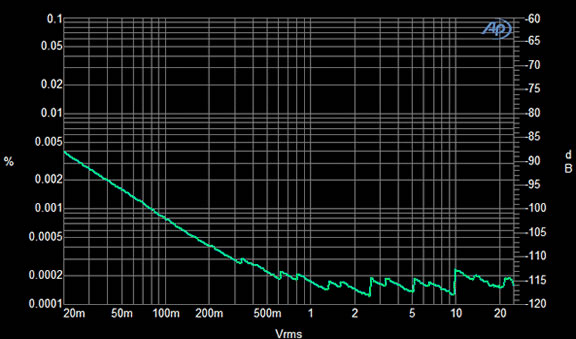
AP2700 system 1 kHz THD+N112 dB, 20 kHz BW
Bandwidth
The analog generator has a bandwidth of 10 Hz to 204 kHz, flat within a few thousandths of a dB across the audio band and only 0.3 dB down at 200 kHz. The analog analyzer has a bandwidth of 10 Hz to 500 kHz, just as flat as the generator and only 0.5 dB down at 500 kHz. What’s out that far? Harmonics, noise, spurious signals, switching components…all key to characterizing audio. By contrast, converter bandwidth is limited to the Nyquist frequency, 1/2 the sample rate. For a 192 kHz converter, the bandwidth ends rather suddenly just below 96 kHz.
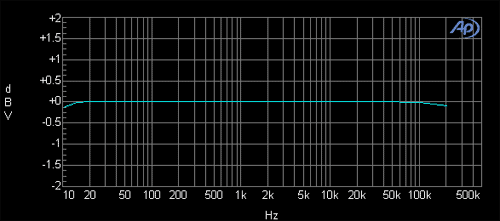
This graph shows the bandwidth of the analog generator plotted on the bandwidth of the analog analyzer
Input Range
We understand that while it is essential to measure tiny amounts of noise and distortion accurately, it is also important to be able to both accept and deliver high audio voltages as well. The 2700 Series has a maximum analog input of 230 Vpk, 160 Vrms [+46.3 dBu] and maximum generator output of 26.66 Vrms [+30.7 dBu].
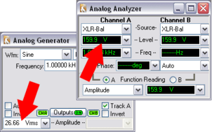
Maximum generator output and maximum analyzer input
Square Waves
Good square waves are critical for testing all types of digital devices. Even at high sample rates, analog square waves generated in digital signal processing (DSP) present an unusable degree of overshoot and ringing, due to the filtering implicit in the DAC output.
On the 2700 Series, a dedicated circuit generates perfectly formed, fast risetime square waves for analog output. This circuit is used even when the digital generator is selected, producing a square wave that is not limited in frequency resolution by sample rate considerations.
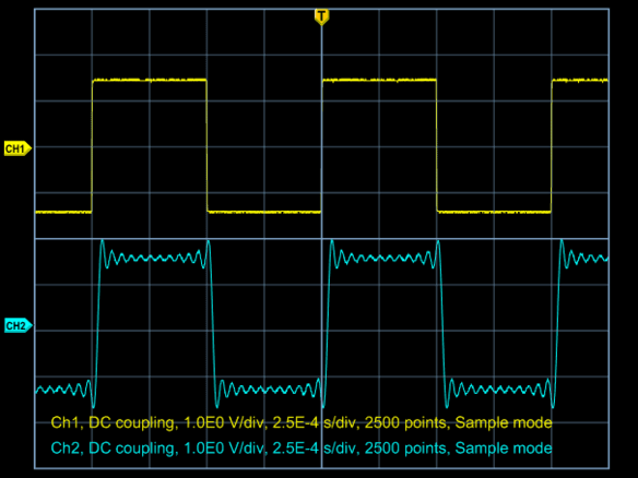
Comparison of a 1 kHz AP2700 analog square wave (top oscilloscope trace) with a square generated in DSP and output through a 96 kHz DAC (bottom trace)