
APx500 Tips: Sequence Steps
With its built-in test sequencer, reporting engine, test limits and pass/fail indicators, Sequence Mode in the APx500 software can be very useful for repetitive audio tests in R&D, product verification and production test applications. One of the most useful features of Sequence Mode is one that new or casual APx users may not yet have discovered: Sequence Steps.
Every measurement in the APx software has a node with a folder icon labeled Sequence Steps, which is collapsed by default to reduce UI clutter (Figure 1a). Clicking on this node will expand it to reveal one or more Sequence Steps (Figure 1b). The list always includes a step with a triangular “play” icon – for example, the Measure Level and Gain step in Figure 1b. This node represents the point in the sequence when the selected measurement will be run. Other Sequence Steps usually have a checkbox, like the Turn Generator On step in Figure 1b. These steps will be executed only if their checkbox is checked.
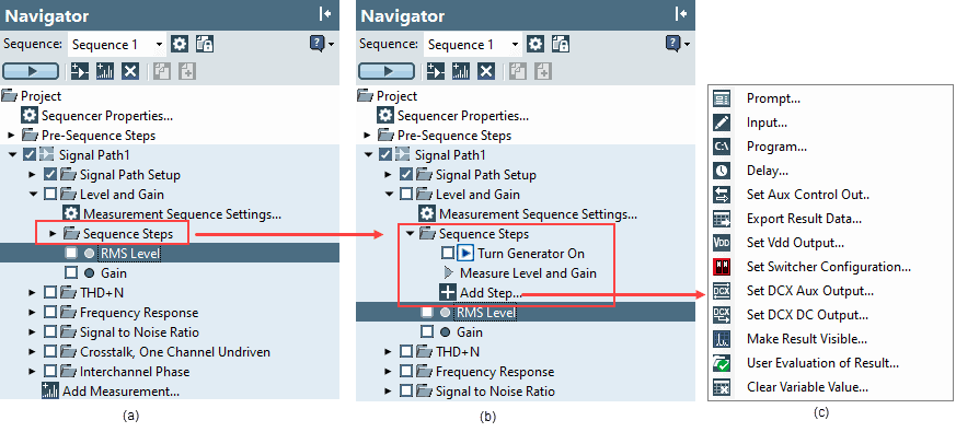
Figure 1. The Sequence Steps node in the Level and Gain measurement.
Clicking the node with the plus sign icon labeled “Add Step…” will display a list of sequence steps that can be added to the current measurement, as shown in Figure 1c. This list is context-sensitive, meaning the steps available will change depending on the specific APx model in use, which digital IO modules are installed, and which input and output connectors are selected. For example, in Figure 1c, there is a step labeled “Set Vdd Output…”. This step is only present for analyzers equipped with a PDM Module. It can be used to set the on/off state and the DC voltage of the PDM module’s Vdd power supply at any point in the test sequence.
In some cases, an item in the list of sequence steps has a dark triangle on the right, indicating the presence of a sub-list. For example, as shown in Figure 2, when configured to test a Bluetooth device, a sequence step labeled Bluetooth appears in the list. Clicking on it opens a sub-list displaying the many Bluetooth sequence steps available. As shown, some of these list items have additional sub-lists.
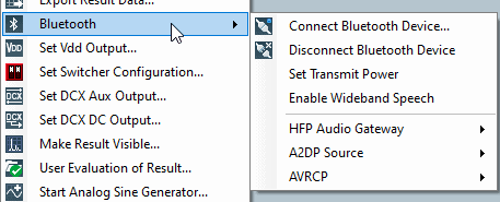
Figure 2. Bluetooth® sequence steps.
Some important attributes of sequence steps are:
- • Sequence Steps with a checkbox are only executed when they have been checked and the measurement is run from the sequencer, meaning either:
- ◊ The measurement’s checkbox has been checked in the selected sequence and the Run Sequence button is pressed, or
- ◊ The measurement is run by right-clicking on it in the Navigator and selecting “Run Selected Measurement.
- • The order of Sequence Steps from top to bottom in each measurement indicates the order in which they will be executed.
- • In any measurement, Sequence Steps can be re-ordered by selecting them and dragging them up or down in the list, or by right-clicking on them and selecting” Move Up” or “Move Down”.
- • Multiple instances of the same type of Sequence Step can be used in any measurement.
- • Sequence Steps can be copied and then pasted on top of another Sequence Step using the right-click context menu. This is often a convenient way to create complicated sequence steps that differ slightly from a previous step.
In addition to measurement Sequence Steps, there are special nodes for Sequence Steps at the beginning and end of the sequence as shown in Figure 3. The Pre-Sequence Steps node at the beginning of the sequence includes the Device ID Prompt – a pre-configured prompt which captures the text entered and assigns it to an APx Variable named DeviceId. The Post-Sequence Steps node contains the Report node (checked by default), which renders, and optionally displays, the test Report at the end of the sequence. The Post-Sequence Steps node also contains a Data Output node, which can be used to append values from any single-value meter measurements like Level or Frequency to a CSV file each time the sequence is run. Additional Sequence Steps can be added to both the Pre- and Post-Sequence Steps nodes.
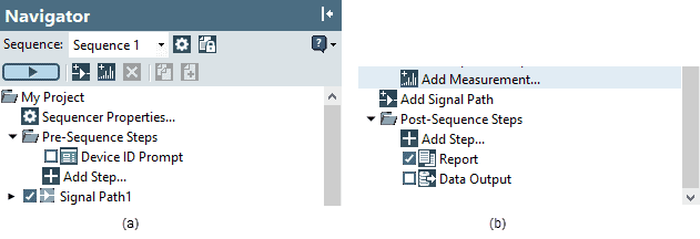
Figure 3. (a) Pre-Sequence Steps and Post-Sequence Steps (b).
An example of a Prompt Sequence Step is shown in Figure 4. Note that standard Windows features can be used to change the font type, size and formatting of the text presented to the test operator. And of course, you can display text in any language. Instructions can be further enhanced by the use of pictures in prompts, as shown. In this example, the scanned barcode will be captured to an APx variable named DeviceId. This text can be used in subsequent Sequence Steps for things like data file names or column headers, etc. There are many APx system variables like this in the software, and users can also create their own variables for this purpose.
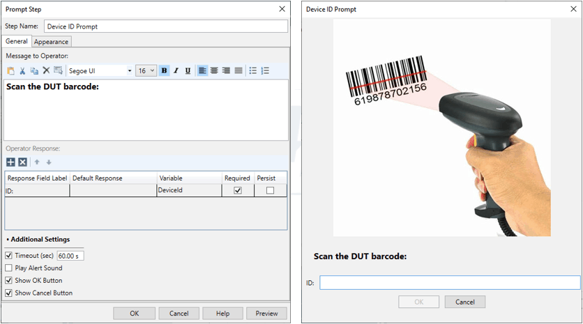
Figure 4. A prompt Sequence Step as configured (left), and as it appears to the user (right).
An APx project can contain multiple Signal Paths, and each one contains a special measurement named Signal Path Setup, where the signal path is configured (Output and Input Connectors, measurement bandwidth, etc.). Prompt Sequence Steps in the Signal Path Setup measurement have some special capabilities. For example, Figure 5 shows a step used to field “calibrate” the ear simulator microphone of a Head and Torso Simulator (HATS) by capturing its output voltage when exposed to a known sound level using a type of sound level calibrator called a pistonphone.
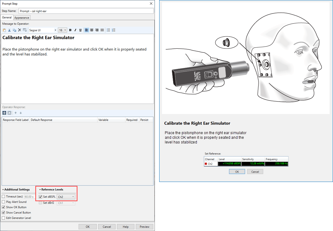
Figure 5. A Prompt Sequence Step in the Signal Path Setup measurement used to capture the sensitivity of an ear simulator.
One of my favorite Sequence Steps is the Run External Program Sequence Step shown in Figure 6. This step can be used to run any PC program that can be invoked from a command line. In this example, the step runs a program called SetVoltage.exe that sets the voltage of an external DC power supply using the user-defined variable named Vdd. The step is configured to wait for the program to finish and check the text string it returns to see if it matches “OK”. If it does, the sequence will proceed. Otherwise, the measurement will fail, alerting the user that something has gone wrong.
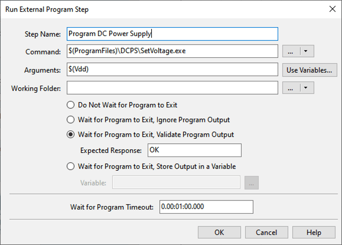
Figure 6. Configuring the Run External Program Sequence Step.
There are numerous Sequence Steps available in the APx500 software for a variety of tasks, such as exporting data, importing limits, controlling switchers, importing EQ curves, etc. We encourage you to make use of this powerful feature to enhance your audio test projects.
Introducing a new way to access all the latest APx500 software versions
Read more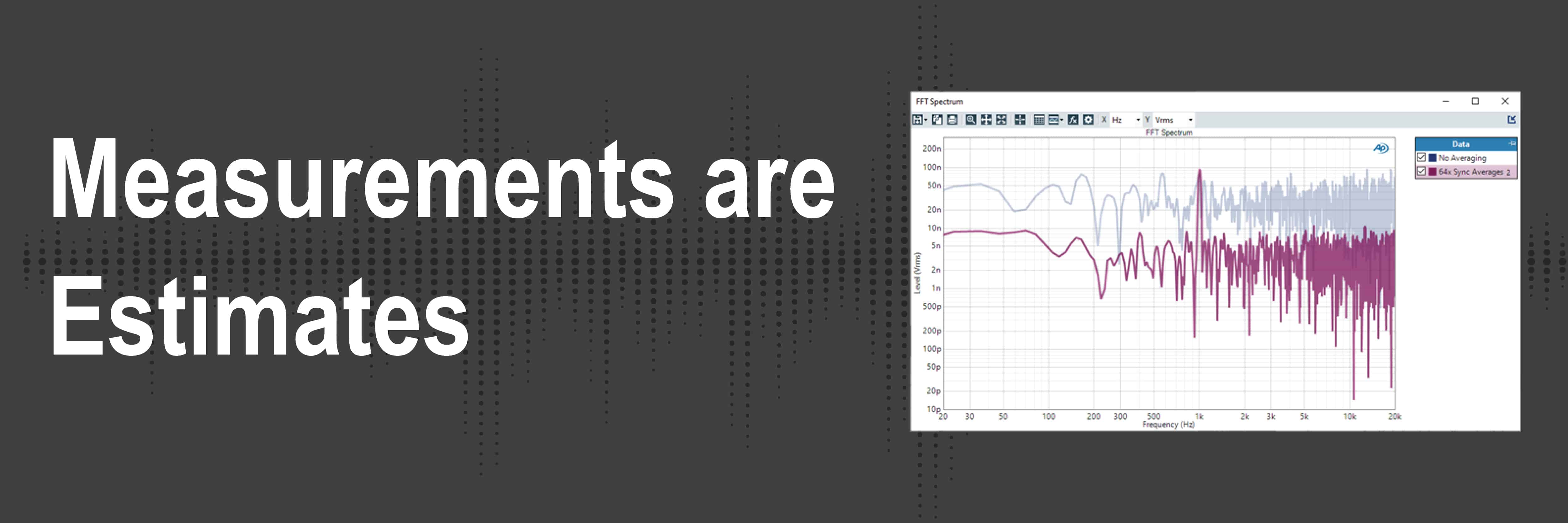
Understand how audio analyzers’ measurements are not absolute truths but are more so estimates.
Read more
If you look at any APx measurement using a log-swept sine stimulus (a chirp), you might notice that the signal is always swept from low to high frequency. Learn more about why chirps are always swept from low to high.
Read more
Benchmarks. They are vital to ensure the R&D team produce a compelling new product or service and are essential on the production line of a manufacturing facility.
Read more