
Hearing Aid Test with APx500 Audio Analyzers
Hearing aids are truly unique from an audio test perspective. They are one of the few audio devices that have both acoustic input and acoustic output, and even the simplest ones have microphones, a power amplifier, digital signal processor, loudspeaker and controls integrated into a tiny, battery-powered package. Add in optional features like noise reduction, microphone arrays/beamforming, telecoils, wireless connectivity, remote control, variable DSP programs, direct audio input and synchronization between left and right sides, and things can get really interesting.
Industry Standards
For air conduction hearing aids, key audio test standards include American standard ANSI/ASA S3.22, Specification of Hearing Aid Characteristics, and Parts 0 and 7 of the IEC 60118 series of international standards, Electroacoustics – Hearing Aids. Part 7 of the IEC 60118 series is nearly identical to ANSI/ASA S3.22; both standards are intended for production test of hearing aids covering the frequency range from 200 Hz to 5 kHz. Part 0 of the IEC 60118 series specifies many of the same tests as IEC 60118-7 and ANSI/ASA S3.22, but it covers a wider frequency range (200 Hz to 8 kHz), and it is intended more for R&D applications such as developing specifications for a new hearing aid model, or qualifying a model of hearing aid for sale in a country or regional jurisdiction.
Test Requirements
For the most part, tests specified in the above hearing aid test standards are part of the feature set typically available in an audio analyzer. For example, they require frequency response measurements at different gain settings, noise level measurements and Total Harmonic Distortion measurements – all standard fare for a good audio analyzer. But there are some aspects of the tests that require special features, or unique results.
The acoustic input and acoustic output nature of hearing aids does offer some challenges. To measure hearing aid output, a special 2 cc acoustic coupler (like the one shown in Figure 1) is required, with a pressure-response measurement microphone. The audio analyzer must also be able to account for the microphone sensitivity, and to display measurement results in acoustic units (Pa or dBSPL).
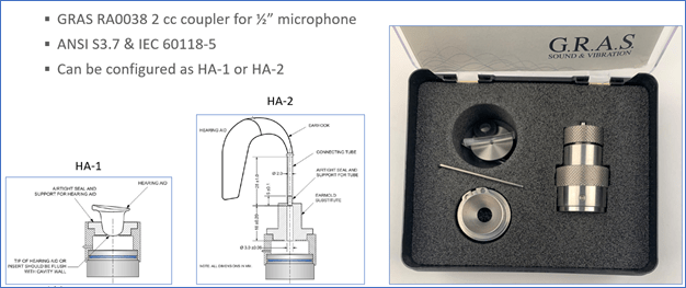
Figure 1. The GRAS RA0038 2 cc coupler can be configured as type HA-1, for In-The-Ear hearing aids or Type HA-2, for Behind-The-Ear hearing aids.
To apply acoustic input signals to hearing aids, the audio analyzer must be able to drive a loudspeaker at a known sound pressure level over a wide frequency range. Even the best loudspeakers have a non-flat frequency response, and their sensitivity can drift with time. As such, it’s important to have a means to “calibrate” the loudspeaker’s output and to equalize it to have a flat response. APx500 audio analyzers can be set to Acoustic Output mode, wherein, once the speaker is “calibrated” and equalized flat, the signal generator level can be specified directly in dBSPL. The APx software also provides tools to flatten a loudspeaker’s frequency response (Figure 2).
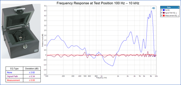
Figure 2. Frequency response of a widely used hearing aid test chamber’s loudspeaker with No EQ, Signal Path EQ and Measurement EQ. Measurement EQ in APx provides the flattest response, but only works with sine-based signals. Signal Path EQ works with any signal, including speech and noise.
APx Hearing Aid Specific Features
There are a few aspects of the ANSI/ASA S3.22 and IEC 60118 test standards that are so specific to hearing aids that we recently (as of version 6.0.1) added new features to the APx500 software to support them.
ANSI S3.22 Fit Limits to Data
One of these new hearing aid-specific features is the “Tolerance method for frequency response” used to construct limits for measured frequency response curves. ANSI/ASA S3.22 and IEC 60118-7 specify that frequency response limits are constructed based on a reference curve for the model of hearing aid being tested. Limits are offset from this curve by ±4 dB in a low-frequency range (up to 2 kHz) and by ±6 dB in a high-frequency range (above 2 kHz). Interestingly, the standards suggest the use of a transparent overlay with the limits drawn at the same scale as the measured frequency response of a unit. (Who uses transparencies these days?!) The limits may be shifted not only in the vertical direction (along the level axis), but also horizontally, by up to ±10% along the frequency axis, until the measured curve is centered within the limits.
Since transparencies have gone the way of the dinosaur, these special limits are now constructed and best-fit to the data algorithmically. Figure 3 shows the new APx ANSI S3.22 Fit Limits to Data derived result, which derives from a measured frequency response curve. The Reference File Path control below the graph is used to specify an Excel or CSV file containing the reference curve for the hearing aid model under test. For convenience, this file path can be specified using APx variables.
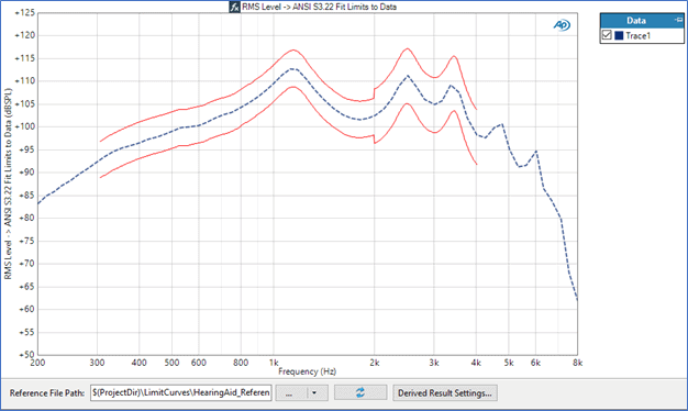
Figure 3. The derived result ANSI S3.22 Fit Limits to Data, which creates limits based on a reference curve and fits the limits to a measured frequency response curve on a best-fit basis.
New IMD Measurements for Hearing Aids
Audio Precision analyzers have had a variety of built-in intermodulation distortion (IMD) measurements since the System One was first introduced over 35 years ago. However, the IMD measurements specified in ANSI/ASA S3.22 and IEC 60118-0 are slightly different from the IMD measurements typically used for audio test. Both standards call for a type of IMD measurement known as Difference Frequency Distortion (DFD) with a difference frequency of 125 Hz. However, specifications such as the swept frequency range, distortion products included and results displayed are slightly different between the two standards and also different from other DFD measurements already included in the APx500 software. Accordingly, we have added two new measurements to Sequence Mode in APx, named “ANSI S3.22 IMD Frequency Sweep” (Figure 4) and “IEC 60118-0 IMD Frequency Sweep” (Figure 5).
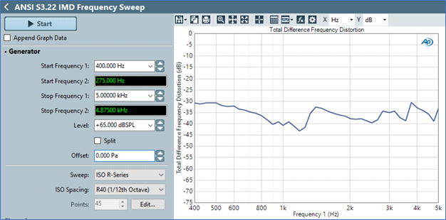
Figure 4. The new ANSI S3.22 IMD Frequency Sweep for hearing aid test in APx.
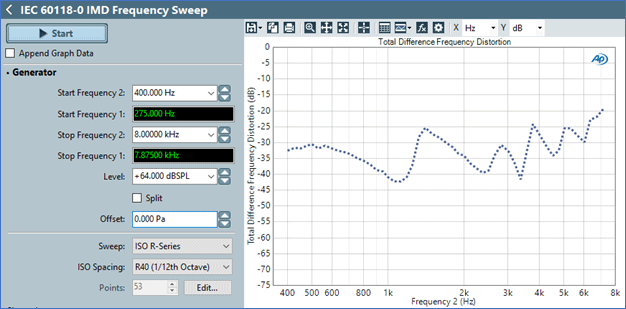
Figure 5. The new IEC 60118-0 IMD Frequency Sweep for hearing aid test.
Readers interested in conducting hearing aid tests with APx500 audio analyzers are encouraged to check out Audio Precision Technote 133. It covers test details as well as equipment requirements, and includes APx project files that work with a variety of APx audio analyzers, not just the APx511 Hearing Instrument Analyzer.
Introducing a new way to access all the latest APx500 software versions
Read more
Understand how audio analyzers’ measurements are not absolute truths but are more so estimates.
Read more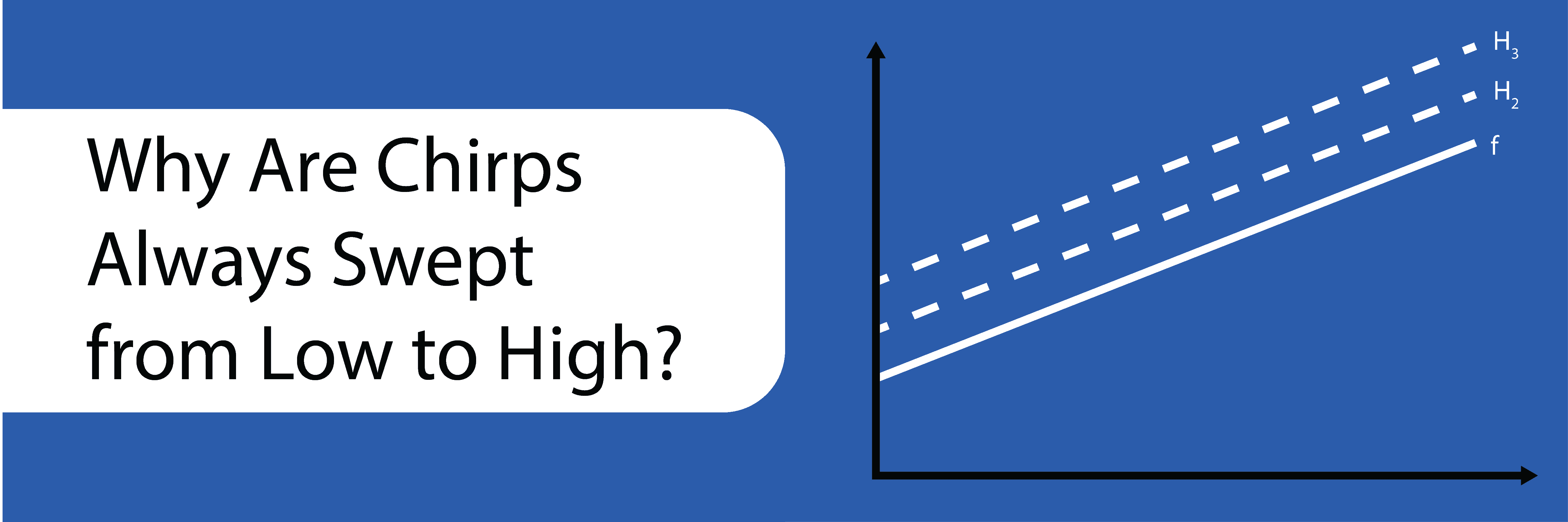
If you look at any APx measurement using a log-swept sine stimulus (a chirp), you might notice that the signal is always swept from low to high frequency. Learn more about why chirps are always swept from low to high.
Read more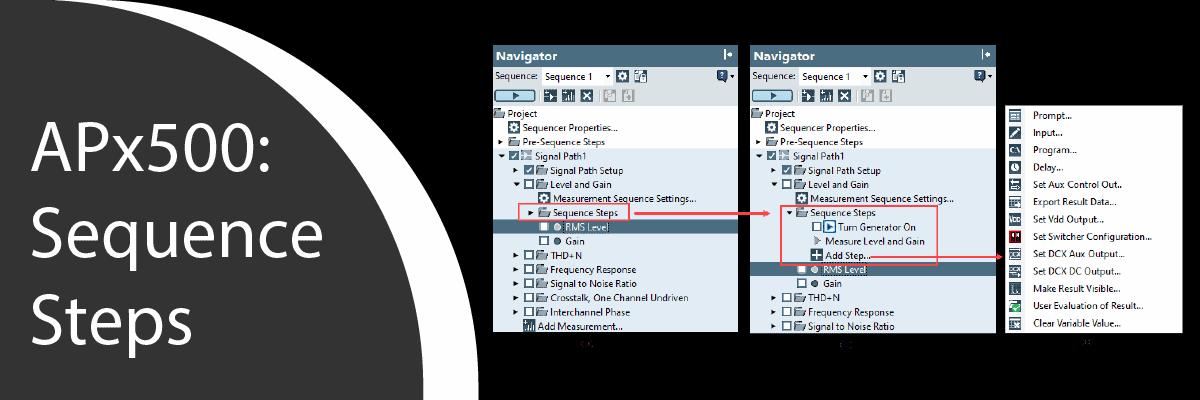
With its built-in test sequencer, reporting engine, and more, Sequence Mode in APx500 software can be very useful for a variety of applications.
Read more