
Loudspeaker Acoustic Measurements in Ordinary Rooms
For loudspeaker frequency response measurements to be meaningful, they must represent the response of the speaker in a free field – an environment free of reflecting surfaces, in which sound can radiate freely in all directions. Some engineers are lucky enough to have access to an anechoic chamber for this purpose, a special room with deep absorptive wedges on all six interior surfaces. But anechoic chambers are very expensive, and not everyone needing to test loudspeakers will have access to one. Fortunately, the Acoustic Response measurement in the APx500 software provides a solution. With its ability to window out reflections, it enables “quasi-anechoic” measurements in an ordinary semi-reverberant room. Depending on the size of the loudspeaker and the size of the room, measurements at frequencies of a few hundred Hz and higher are possible.
Time-selective or quasi-anechoic techniques work by windowing out reflections from the impulse response before applying a Fourier transform to it to obtain the frequency response. For a discussion of some of the theory behind these techniques, please see our Application Note on Loudspeaker Electroacoustic Measurements.
The room should have a low level of ambient noise over the frequency range of interest, and it should be very large compared to the loudspeaker’s dimensions. To see why it should be large, consider the sketch in Figure 1. The measurement microphone is positioned on-axis at a distance d from the loudspeaker. The microphone should be in the “far field” of the loudspeaker – far enough away from it that the sound field is stable and behaves in a predictable way. One rule of thumb is that the far field of a sound source begins at a distance of about three times the largest dimension of the source (shown as M in Figure 1). And some experts think it should be more like ten times the largest dimension. Hence, the larger the speaker, the larger the required room.
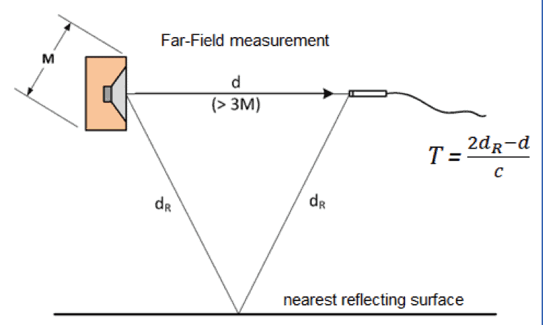
Figure 1. Schematic of loudspeaker on-axis measurement showing the direct sound path and the path of the nearest reflection.
The direct sound travels distance d from the DUT to the microphone in Figure 1, but there is also a reflection from the nearest surface (floor, ceiling or wall) that travels distance 2dR. The difference in time of arrival between the direct sound and the closest reflection is
T = (2dR – d)/c, where c is the speed of sound in air (about 344 m/s at room temperature). For a small loudspeaker in a typical room with a ceiling height of 8 to 10 ft (2.4 to 3.0 m), time T is typically about 5 to 6 milliseconds.
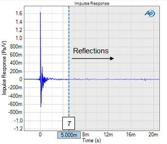
Figure 2. A loudspeaker's measured Impulse Response with the time window cursor positioned at T = 5 ms after the main impulse.
Reflections are visible as small impulses that occur sometime after the main impulse. They are typically difficult to see in the Impulse Response (Figure 2), but quite prominent in the Energy Time Curve (Figure 3). The Energy Time Curve represents the envelope of energy contained in the impulse response, with its magnitude expressed on a decibel scale. For example, in Figure 3 there are several small secondary peaks beginning at about 6 ms after the main impulse, which are indicative of reflections.
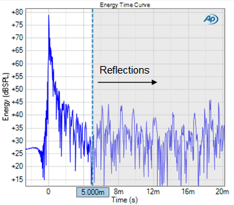
Figure 3. The Energy Time Curve result.
In Figure 2 and Figure 3, the time window cursor (vertical dashed line) is positioned at 5 ms, and the area to the right of the cursor is shaded grey. The APx software recomputes the RMS Level result whenever the time window cursor is moved to a new position (or a new time window value is entered).
Figure 4 shows the RMS Level results for a loudspeaker tested in an anechoic chamber with the time window set at 5 ms (blue trace) and 1.0 s (magenta trace). The time window cursor and shading in Figure 4 correspond to T = 5 ms or 1/T = 200 Hz).The shading is intended to indicate that the RMS Level result is inaccurate below frequency 1/T (200 Hz in this case). But note that this is just an approximation. As shown, the windowed response is off by about 2 dB right at 200 Hz and it is only very close to the true response from about 400 Hz and above. Also, the smoothing effect of the windowing extends much higher in frequency – up to about 1 kHz.
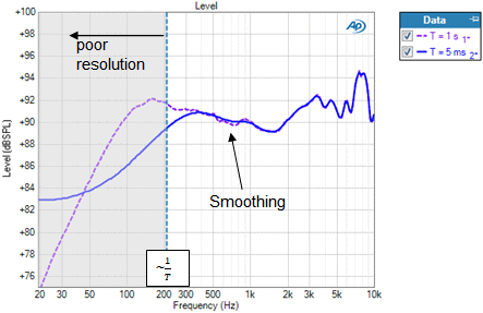
Figure 4. The RMS Level result with curves corresponding to time windows of 1.0 s and 5 ms after the main impulse.
Quasi-anechoic measurements are quite useful in spite of this low-frequency limitation, because they are fast and enable essentially free-field measurements over much of the audible frequency range in an ordinary room.
Some other tips when setting up loudspeaker measurements are:
- - Most rooms are rectangular in shape. Orient the loudspeaker and microphone on the diagonal of the room rather than parallel to the walls, to further reduce the strength of wall reflections.
- - For 2-way and 3-way loudspeaker systems, unless a measurement reference axis is specified, point the microphone at the tweeter, because high frequencies are much more directional than low frequencies.
Learn about applications, and you’ll get tips and tricks of test and measurement
Read more
Benchmarks. They are vital to ensure the R&D team produce a compelling new product or service and are essential on the production line of a manufacturing facility.
Read more
Introducing a new way to access all the latest APx500 software versions
Read more
Understand how audio analyzers’ measurements are not absolute truths but are more so estimates.
Read more