
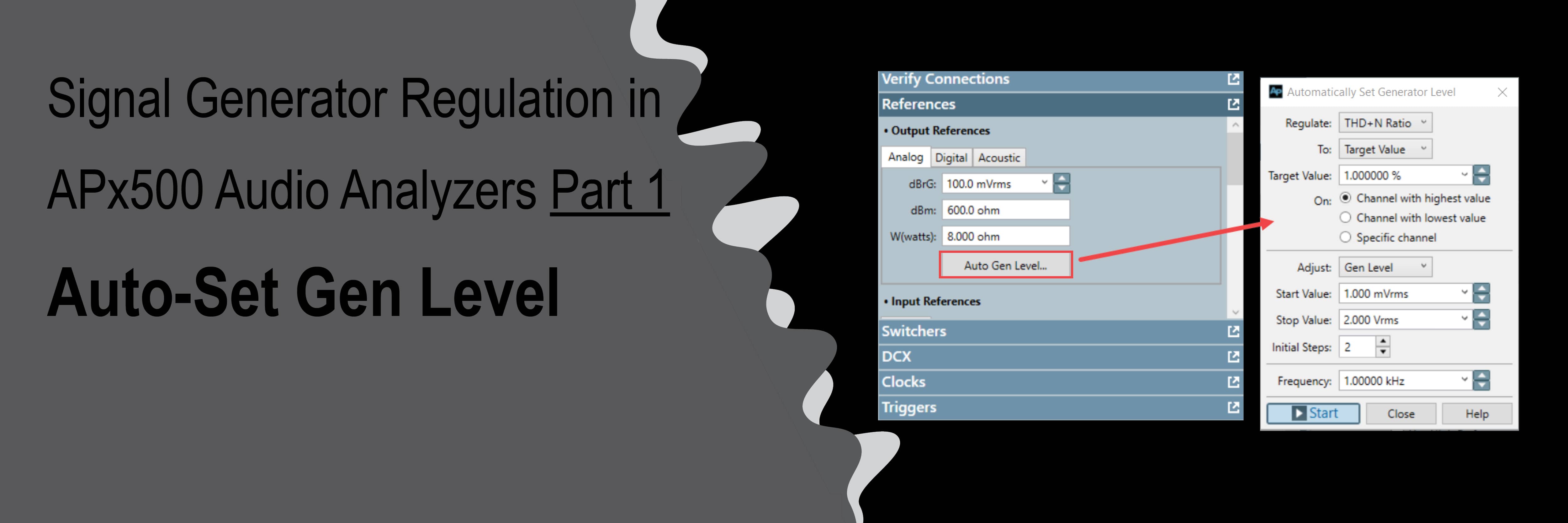
Signal Generator Regulation in APx500 Audio Analyzers – Part 1: Auto-S
Introduction
Automatic regulation of an audio analyzer’s signal generator is one of many useful but not well-known features of APx500 software. We’re often faced with the need to adjust an attribute of the signal input to a device under test (DUT) such that an attribute of the output from the DUT precisely meets a required condition. For example, perhaps we want to automatically find maximum output level of a power amplifier or set a speaker or mouth simulator to generate a specific acoustic sound pressure level. In Part 1 of this two-part series, we’ll discuss one of the main regulation tools in the APx500 software – the Auto-Set Gen Level feature. In Part 2 we’ll cover other measurements specifically aimed at regulation in Sequence Mode and Bench Mode.
Example Use Case – Power Amplifiers
Amplifier power rating is a classic example of signal generator regulation. The maximum power rating of an amplifier is typically specified as its measured output power at a distortion level (THD+N ratio) of one percent, when stimulated with a mid-frequency pure tone (e.g., a 1.0 kHz sine signal). A test specification might require that several audio quality metrics (gain, frequency response, SNR, crosstalk, etc.) be measured at rated power, or some percentage of rated power. Hence, we need to first determine the generator level corresponding to rated power, then apply this generator level to subsequent audio tests.
Consider Figure 1, a plot of measured THD+N versus Generator Level for a small headphone amplifier measured with a stepped level sweep from 1 mVrms to 1.6 Vrms at 1.0 kHz. This curve has a classic shape that is typical of all power amplifiers: At low input levels (1 mVrms to about 200 mVrms in this case), the THD+N is dominated by noise, so the curve slopes downward with increasing level. In the range from about 200 mVrms to 1.2 Vrms, the THD+N is lowest (indicating the optimum operating range for this DUT), and above 1.2 Vrms, the THD+N abruptly increases from about 0.02% to 10%. The breakpoint at the generator level of 1.2 Vrms corresponds to the onset of clipping. As the input voltage is increased beyond this point, the DUT output begins to clip, causing distortion that rapidly increases with generator level.
To determine the rated power, we need to find the generator level corresponding to an output THD+N of 1.0%. We could find the required generator level by interpolating the curve in Figure 1. Another approach might be by trial and error - manually changing the generator level while observing the THD+N Ratio result, until the required distortion value is measured. But with such a steep slope after the onset of clipping, finding the target level manually would be quite time-consuming. Fortunately, APx500 audio analyzers have some useful tools for solving such regulation problems.
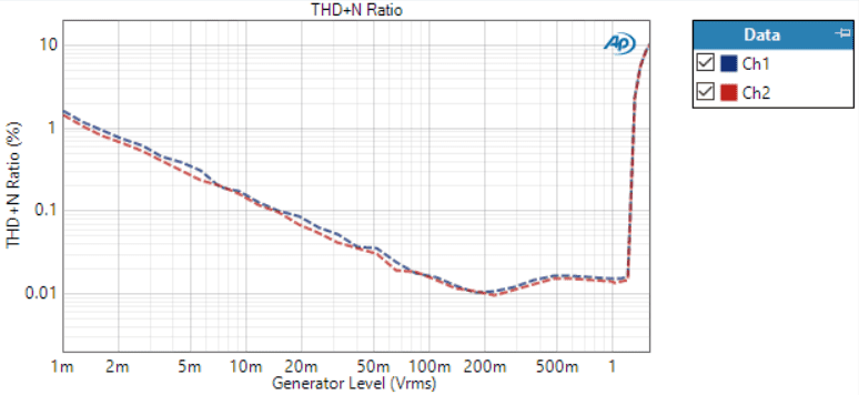
Figure 1. Measured THD+N Ratio (20 Hz - 20 kHz) of a headphone amplifier, stepped level sweep from 1 mV rms to 1.6 Vrms at 1.0 kHz.
Auto-Set Gen Level
The first regulation tool in an APx we’ll discuss is the “Auto-Set Gen Level” feature (a shortened version of Automatically Set Generator Level). This is accessed from the References sub-panel of Signal Path Setup in both Sequence Mode and Bench Mode (Figure 2). It is used to adjust the generator level of a sine signal input to a DUT to find a specified Target Value of RMS Level or THD+N at the output of the DUT.
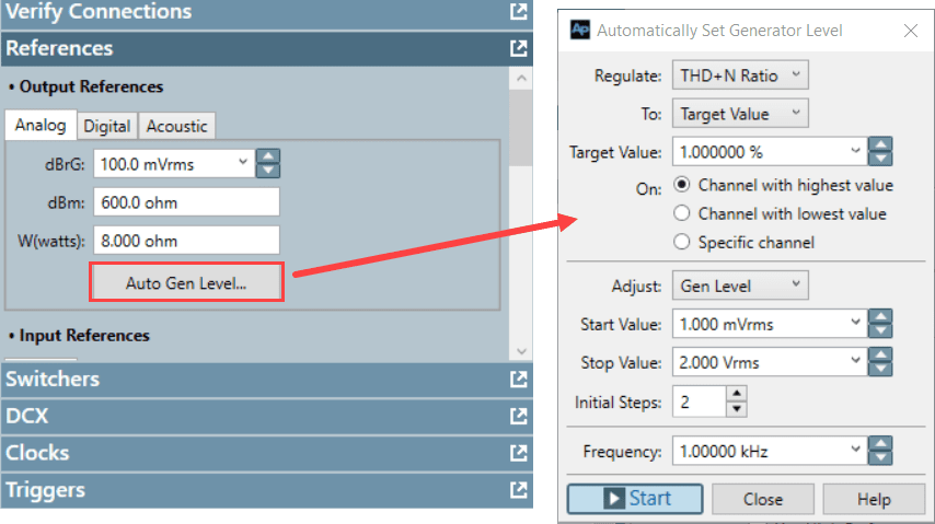
Figure 2. The Auto Gen Level button in the References sub-panel of Signal Path Setup opens the Automatically Set Generator Level dialog.
The top part of the Automatically Set Generator Level dialog is used to specify parameters of the regulation target: You can select:
- -Regulate: (THD+N Ratio or RMS Level)
- -To: (a Target Value, Maximum Value or Minimum Values)
- -On: (Channel with highest or lowest value, or a Specific channel)
Note: The units of the Target Value match the units of the Regulate parameter; i.e., if Regulate is set to THD+N Ratio, the Target Value is specified in percent, dB or x/y; if RMS Level is selected, Target Value units are Vrms, watts, etc. in the voltage family of units, or dBSPL or Pa, if the input mode is Acoustic.
The lower part of the Automatically Set Generator Level dialog is used to specify parameters of the generator that will be automatically adjusted (usually Generator Level). The Start Value and Stop Value controls specify the minimum and maximum levels to be used during the regulation process. The Auto-Set Gen Level feature uses an algorithm to find the Target Value by efficiently adjusting the Generator Level within the range between Start Value and Stop Value. But, for the algorithm to succeed, the Target Value must occur somewhere between the specified generator Start and Stop values. Note: The Stop Value can be higher than the Start Value or lower than it, in which case the search direction will be reversed.
The Initial Steps control specifies the number of steps the algorithm first uses to go from the Start Value to the Stop Value, when searching for the Target Value. The minimum value is 1 and the default value is 2. Higher values allow the allow the algorithm to approach the stop value more gradually, which may improve performance in some situations. Finally, the Frequency control specifies the frequency of the sine signal to be generated.
When all the parameters have been set as required, simply click the Start button. Using the specified parameters, the system will automatically adjust the generator level and measure the DUT output Level or THD+N until the specified Target Value is achieved, within a tolerance. (For simplicity, the tolerance value is fixed internally.) If the Target Value is found (success), the following occurs:
- 1. The generator is left on generating a sine signal at the Level which produced the Target Value and Frequency as specified in the dialog. For example, see Figure 3. In this case the DUT (headphone amplifier) had a measured THD+N of 1.001% on output Channel 1 at a Generator Level of 1.256 Vrms.
- 2. The dBrG Output Reference is automatically set to the Generator Level which caused the Target Value (1.256 Vrms for the headphone amplifier in this example).
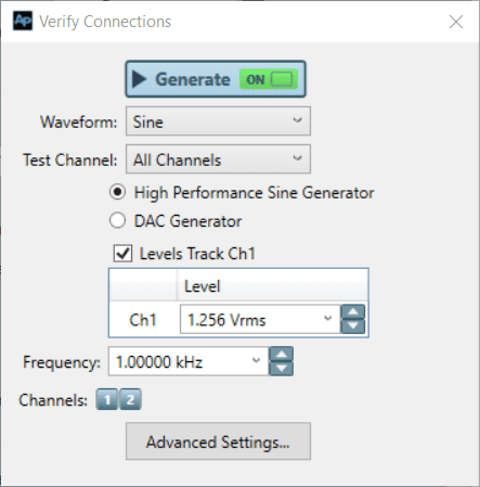
Figure 3. The Verify Connections sub-panel after the Auto-Set Gen Level process completed successfully.
Item 2, above is a very useful feature, because after regulation, setting the generator level to 0 dBrG in any measurement of the same signal path will set the generator to the Level that caused the Target Value. For example, to test metrics like frequency response, SNR, gain, etc. of a power amplifier at rated power (1% THD+N), you need only use Auto-Set Gen Level to find the 1% THD+N Target Value, then run the required measurements in the same Signal Path with the Generator Level set to 0 dBrG.
As mentioned above, for the Auto-Set Gen Level process to succeed, the Target Value must occur somewhere between the specified generator Start and Stop values. If it doesn’t, the regulation will fail after 19 regulation steps are tried. For example, referring to Figure 1, if we specified a THD+N Ratio Target of 1.0%, with a Start Value of 5 mVrms and a Stop Value of 500 mVrms, the regulation process could never succeed, because the THD+N Ratio would never reach the Target Value within this range. When this happens, the error message shown in Figure 4 is displayed. Clicking the Details button will display the Regulation history (the generator Levels tested and the corresponding DUT output), as shown.
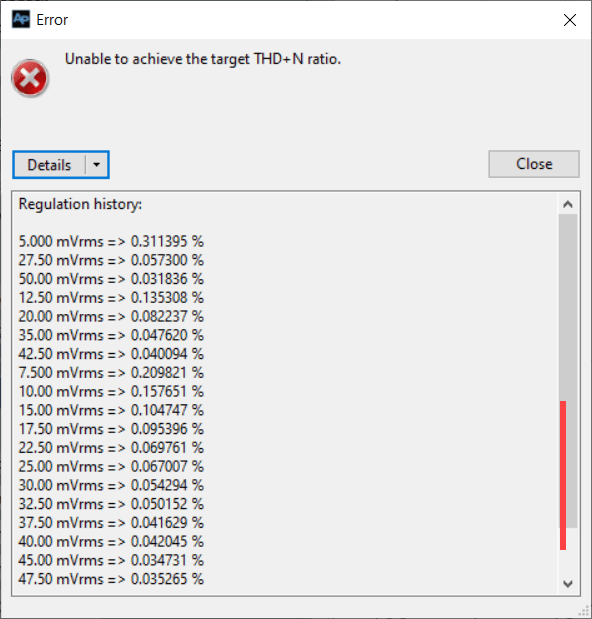
Figure 4. The error message displayed when Auto Set generator Level fails to find the Target Value.
To ensure that the Auto-Set Gen Level process succeeds in finding the Target Value, it’s important to choose appropriate Start and Stop Values. The easiest way to do this in Sequence Mode is by manually adjusting the Generator Level in the Verify Connections sub-panel while observing the RMS Level or THD+N Ratio result in Signal Path Setup. In Bench Mode, you can manually adjust the Level in the Generator Panel while observing the THD+N or RMS Level meter. This way, it’s easy to find a start and stop level such that the Target Value occurs between them. An alternative to this manual method is to run a Stepped Level Sweep measurement, as illustrated in Figure 1. However, this method also requires choosing appropriate start and stop levels for the sweep, which will likely require resorting to the manual method, anyway.
Regulation in a Sequence
There’s a feature that can be used to regulate the generator automatically in Sequence Mode. Clicking on the gear-shaped icon labeled “Measurement Sequence Settings…” in Signal Path Setup invokes a dialog of the same name. This dialog contains a checkbox labeled Auto Set Generator Level. When checked, the Auto Set Gen Level feature is automatically run using the parameters as set in the Automatically Set Generator Level dialog (Figure 2). With this feature you can easily create a sequence to automatically find a generator level that results in a target THD+N Ratio or RMS Level, then run a series of measurements at that level and produce a report.
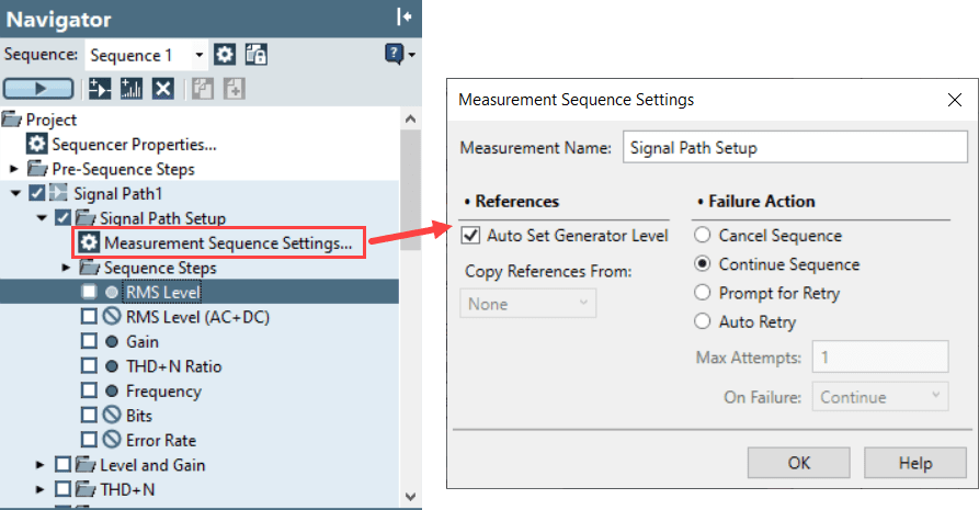
Figure 5, Clicking on the Measurement Sequence Settings node in Signal Path Setup invokes a dialog containing an Auto-Set Gen Level checkbox.
Conclusion
This concludes our discussion of the Auto-Set Gen Level feature in APx. In addition to standard power amplifier testing, the feature is valuable for many use cases, including:
- - Testing power amplifiers with digital inputs
- - Calibrating the acoustic output level of a speaker
- - Headphone characteristic input (the input level resulting in output level of 94 dBSPL at 500 Hz in an ear simulator)
In Part 2 of this post, we’ll discuss other measurements in Sequence Mode and Bench Mode which are specifically used for regulation.
Measurements specifically aimed at regulation in Sequence Mode and Bench Mode as part of the Signal Generator Regulation on APx500 2 part post
Read more
An APx515 customer asked, what’s the right way to load the analog generator output of the APx515? Especially: What is the lowest resistive load allowable for the generator output? What is the output impedance of the generator output?
Read more

The APx500 software is a powerful tool that offers users the flexibility and control needed to automate, integrate, and customize their audio testing processes in a wide array of scenarios. By understanding the capabilities of the APx500 software and its API, you can leverage them to streamline your workflows, enhance productivity, and create custom solutions tailored to your specific requirements.
Read more