
Created on 2009-02-24 11:03:00
Question:
We want to use the APx585 to test some older professional audio equipment that is specified using a signal generator with a 600 Ω output impedance. The APx585 only offers a fixed 100 Ω output impedance. What can we do?
Answer:
Unlike its 2 and 4-channel cousins, the APx520/525 and 521/526, which offer 40, 100, 150, 200, and 600 Ω output terminations, the balanced outputs of the APx585 and 586 are fixed at 100 Ω. This is due to the high channel count in these units—there just wasn't enough room to add the resistors and relays to make all the output termination choices available. It's easy, however, to achieve 600 Ω output impedance by using external resistors. The most convenient way to do this is to mount the resistors inside an XLR barrel adapter, such as the Switchcraft S3FM (Figure 1).

Figure 1 Switchcraft S3FM barrel adapter.
Not only is this convenient, but putting the resistors in individual barrels prevents crosstalk problems. You will need one adapter for each channel to be converted. The wiring diagram is shown in Figure 2. For balanced outputs, each of the two terminals of the balanced connection should have one half of the impedance. Since we are adding 500 Ω to the 100 Ω that already exists, two 250 Ω resistors are required. We recommend 250 Ω 1 Watt resistors with a tight 0.1% tolerance. You should use heat shrink or tubing on the resistor leads to prevent shorting, and connect pin 1 (ground) to the shell terminal of the adapter at the female end.

Figure 2 Barrel wiring diagram. R=250 Ohms.
To connect the adapters to the APx585/586 audio analyzer, you can use the DB25M to 8-XLR male cables (see Figure 3) included in the CAB-585 cable kit.
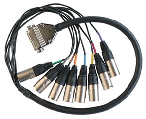
Figure 3 DB25M to 8-XLR male.
SLX #4083
JB