Switching Amplifier Measurement Filters
Providing signal preconditioning for measurement accuracy in Class-D amplifier test
The Audio Precision AUX-0025 / 0040 / 0100 switching amplifier measurement filters are designed to be inserted between the device under test and an analyzer input, to reduce out-of-band switching signal components before measurement. The filters use a passive design for optimal performance, with custom inductors designed for high power handling and minimal low-frequency distortion.
The AUX-0025 is a two-channel passive filter, with a 20 Hz to 20 kHz passband. It is designed to be used with two-channel analyzers, including the APx555, APx52x Series and 2700 Series test systems.
The AUX-0040 is a two-channel passive filter, with a 20 Hz to 40 kHz passband. It is designed to be used with two-channel analyzers, including the APx555, APx52x Series and 2700 Series test systems.
The AUX-0100 is an eight-channel passive low-pass filter, with a 20 Hz to 20 kHz passband. It is designed for use with the APx58x Series audio analyzers.
Manufacturers of power amplifiers are moving to switching designs (also called Class D or switch-mode) to make their amplifiers lower cost and more efficient compared to conventional linear power amplifier designs. This technology has particular appeal in automotive and personal stereo applications where efficiency, low battery consumption, small size, and low cost are desired. However, amplifiers using this technology present new measurement challenges.
The switching process adds fast rising edges at the switching frequency to the audio output signal. These fast edges are of no consequence to the typical load (a loudspeaker), but present a difficult signal for measurement instruments. The fast switching edges present high energy content and will introduce slew rate limiting when presented to the input stage of most measurement instruments. When stressed by these fast edges, the analyzer input amplifier will usually slew rate limit and will not be able to function effectively in its normal mode. Auto ranging will be affected and the signal under test will be misrepresented to the following measurement circuits. The result is that noise and distortion measurements of switching amplifiers with almost any analyzer without preconditioning will yield inaccurate and unpredictable results.

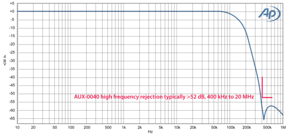
AUX-0040 high frequency rejection

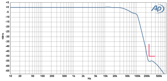
AUX-0025 & AUX-0100 high frequency rejection
SPECIFICATIONS
Number of Channels
2 (AUX-0025 & AUX-0040)
8 (AUX-0100)
Frequency Response
±0.05 dB, 20 Hz to 20 kHz (AUX-0025 (dc coupled) & AUX-0100 (ac coupled))
±0.08 dB, 20 Hz to 40 kHz (AUX-0040 (dc coupled))
Insertion Loss
Typically −0.054 dB
High-Frequency Rejection
Typically > 50 dB, 250 kHz to 20 MHz (AUX-0025 & AUX-0100)
Typically > 52 dB, 400 kHz to 20 MHz (AUX-0040)
Maximum Input
±200 Vpk [140 Vrms], dc to 7.5 kHz, decreasing to 75 Vpk [53 Vrms] from 20 kHz to 2 MHz (AUX-0025 & AUX-0100)
±200 Vpk [140 Vrms], dc to 15 kHz, decreasing to 75 Vpk [53 Vrms] from 40 kHz to 2 MHz (AUX-0040)
Interchannel Crosstalk
90 dB at 20 kHz (AUX-0025 & AUX-0040)
82 dB at 20 kHz (AUX-0100)
Distortion
< -110 dB harmonic (measured at 70 Vpp, 1 kHz)
< -100 dB IMD (at 70 Vpp with 18 kHz and 20 kHz dual-tone test signal)