
Jitter Measurements with APx
Jitter in digital audio systems may cause audible distortion in the form of jitter sidebands in the output signal. Jitter tolerance testing can reveal jitter induced distortion but is often neglected in the design of circuits and components because it is difficult and time consuming. Audio Precision APx analyzers provide jitter generation and jitter analysis features to simplify jitter testing.
What is Jitter?
Jitter is the variation in the time of an event—such as a regular clock signal — from nominal. For example, the jitter on a regular clock signal is the difference between the actual pulse transition times of the real clock and the transition times that would have occurred had the clock been ideal and perfectly regular. Against this nominal reference, the zero-crossing transitions of many of the pulses in a jittered data stream are seen to vary in time from the ideal clock timing. Jitter is phase modulation of the digital interface signal.
The jitter component can be extracted from the clock or digital interface signal to be analyzed as a signal in its own right. Among the more useful ways of characterizing jitter is examination of the jitter frequency spectrum and identifying the significant frequency components of the jitter itself.
Time Domain and Frequency Domain Jitter Measurements with APx
Jitter amplitude, then, is a measure of time displacement and is expressed in units of time, either as fractions of a second or unit intervals (UI). Jitter frequency is the rate at which this phase-shifting is taking place. Like other noise or interference signals, the jitter modulation signal can be a pure and regular sine wave, a complex waveform or have a completely random character.
Measuring Jitter with APx
APx analyzers configured with the Advanced Master Clock option (APX-AMC) can generate audio and calibrated jitter on digital output ports or clock master outputs on receiver ports (for example, bit clock outputs on a digital serial receiver input) and measure jitter on digital serial receiver bit clock inputs.
The APx jitter generator provides control of jitter amplitude in seconds or unit intervals, waveform type (sine, square, or noise), frequency, and source (Apply To). The jitter generator amplitude is calibrated in terms of peak level in seconds or UI.
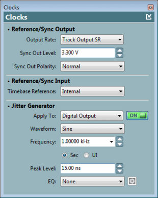
The APx Clocks Panel Jitter Generator Settings
The APx jitter analyzer measures jitter with frequency filtering and choice of units (seconds or UI). The APx input configuration supports jitter measurement filtering with High-pass, Low-pass, Weighting, and Equalization.
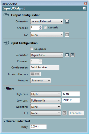
APx Input/Output panel settings with Jitter (sec) measurement filter
D-to-A Jitter Tolerance Tests
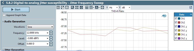
Jitter tolerance is a measure of the tolerance of a device to input jitter. Digital converters are susceptible to clock jitter, which can be tested by jittering the digital input or clock to the device and measuring output audio distortion caused by the jitter. The APx measurement software simplifies jitter tolerance testing with sweeps of output jitter (either master clock output at the Sync Output if the device is synchronized to an external clock, or jittered digital audio) and measurements of the device’s output THD+N.
An example test of a Digital-to-Analog converter is shown below with a nested sweep of jitter frequency and audio frequency versus measured THD+N, according to the method specified by the AES-17 standard. For this particular converter, with a jitter amplitude of 40 ns, at a given audio frequency the jitter tolerance is unchanged as jitter frequency increases.
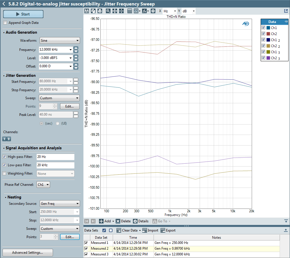
D-to-A Jitter Tolerance Test according to AES-17 (click to zoom)
A-to-D Jitter Tests
Figure 5 below illustrates a jitter spectra of the output of a high performance A-to-D converter operating at 48 kS/s with 997 Hz analog sine wave and square wave audio signals applied to the input. The jitter magnitude is expressed in UI. Jitter at the 24 kHz folding frequency is absent with the sinewave input, but prominent with the square wave input.
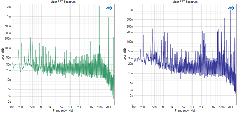
APx Signal Analyzer measurements of A-to-D digital output jitter spectra with 0 dBFS 997 Hz sinewave (green) and square wave (blue) audio inputs.
APx Analyzer Configurations for Jitter Measurements
Jitter measurements are available for APx analyzers configured with the Advanced Master Clock option (APX-AMC). The Advanced Master Clock hardware provides the jitter generator and jitter analyzer hardware that operates in conjunction with jitter-enabled digital hardware options, such as the Advanced Digital I/O (APX-ADIO), Programmable Serial I/O (APX-PSIO), and Pulse Density Modulation (APX-PDM) interface options. These interfaces and the Advanced Master Clock option can be added to existing APx Series audio analyzers (except the APx515). Contact your Audio Precision sales partner for details.