

The “Big Six” Audio Measurements – Part II
In a previous blog post regarding “The Big Six” measurements of audio test, we defined three of these very important measurements: level, frequency response, and THD+N. The remaining measurements of “The Big Six” include the following:
• Phase
• Crosstalk
• Signal‑to‑Noise Ratio
Below are definitions of these three vital measurements. Keep in mind that different applications, devices, and processes require different approaches for test and measurement procedures.
Phase
In audio engineering, phase measurements are used to describe the positive or negative time offset in a cycle of a periodic waveform (such as a sine wave) measured from a reference waveform. (Visit our blog post, “Why Sine Waves” to learn more). The reference is usually the same signal at a different point in the system, or a related signal in a different channel in the system.
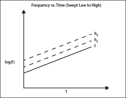
Figure 1: Demonstration of two channels being out-of-phase.
This choice of references defines the two most common phase measurements: device input/output phase, and interchannel phase. Phase shift varies with frequency, and it is not uncommon to make phase measurements at several frequencies or to plot the phase response of a frequency sweep. Phase is expressed in degrees.
Crosstalk
In audio systems of more than one channel, it is undesirable for the signal in one channel to appear at a reduced level in the output of another channel. This signal leakage across channels is called crosstalk, and in practical devices it is very difficult to eliminate. Crosstalk is expressed as the ratio of the undesired signal in the unstimulated channel to the signal in the stimulated channel. Crosstalk is largely the result of capacitive coupling between channel conductors in the device, and usually exhibits a rising characteristic with frequency.
Signal-to-Noise Ratio
How much noise is too much? That all depends on how loud your signal is.
Signal-to-noise ratio (or SNR) is a measure of this difference, providing (like THD+N) a one-number mark of device performance. The signal is usually set to the nominal operating level or to the maximum operating level (or MOL) of the DUT. When SNR is made using the MOL, the result can also be called the dynamic range, since it describes the two extremes of level possible in the DUT. (Dynamic range in digital devices has a somewhat different meaning). SNR is usually stated in decibels, often shown as negative.
Using traditional methods, SNR requires two measurements and a bit of arithmetic. First you measure the signal level, then turn off the generator (and often, terminate the DUT inputs in a low impedance as well, to fully reduce the noise in the device). Then the noise level (often called the noise floor) is measured, using filters to restrict the measurement bandwidth. The ratio between the two is the SNR.
From R&D to production lines, the audio measurements used in different applications will require various methods of evaluation. Establishing benchmarks and adhering to a process of assessment for each DUT will provide engineers with the insights to make the right decisions on product development and creation.
To learn more about “The Big Six” measurements of audio, check out Part I.

In audio test, there are a small number of performance benchmarks that are most important when evaluating a device-under-test (DUT). We call them “The Big Six” measurements.
Read more
Benchmarks. They are vital to ensure the R&D team produce a compelling new product or service and are essential on the production line of a manufacturing facility.
Read more
Introducing a new way to access all the latest APx500 software versions
Read more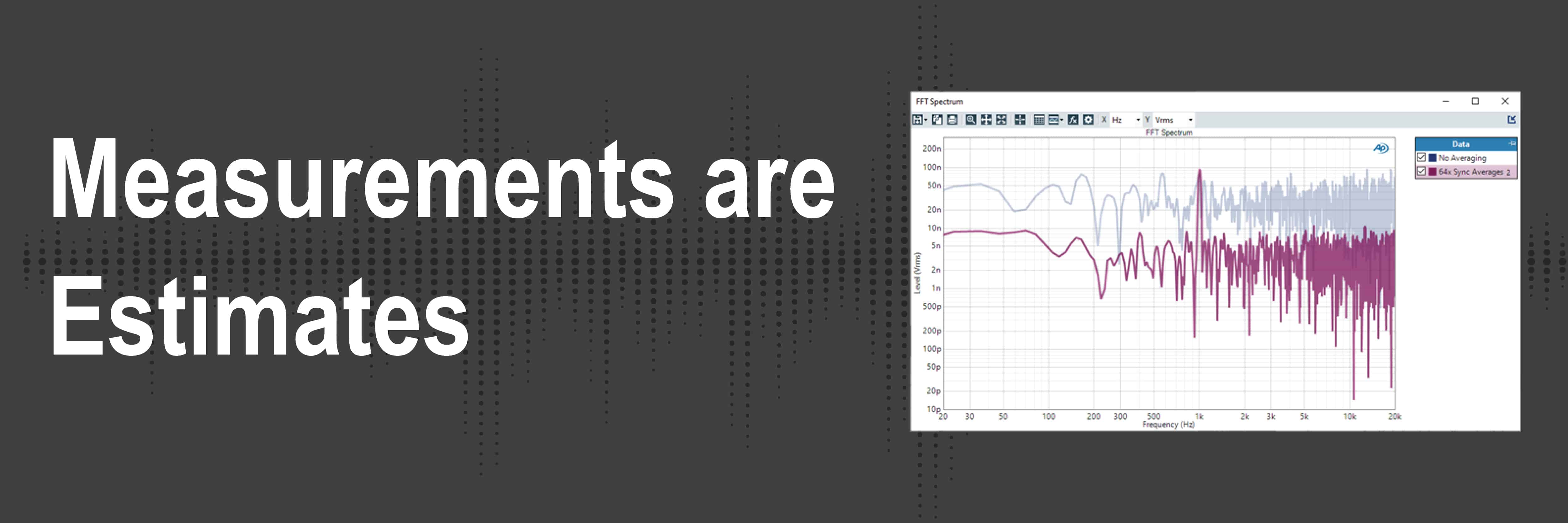
Understand how audio analyzers’ measurements are not absolute truths but are more so estimates.
Read more