Created on 2011-07-20 19:20:00
Clicks and pops in the output of audio equipment can be annoying, as well as be potentially dangerous if a user is listening on headphones. These unwanted noises will typically occur when a unit is turned on, turned off, switched, or muted. While many audio IC solutions have integrated click and pop suppression, some circuits still require suppression measures to be taken.
We’ve designed two APx projects that utilizes our APx Sound Level Meter Utility to do click and pop detection, taking advantage of the file recording capability of the APx500 software. This solution is superior to making measurements at discrete intervals. Even at a relatively fast measurement rate of 128/sec, a transient click or pop can get missed between acquisitions. By making a digital recording at a 48 kHz sample rate, we can be sure that any audible transients will get captured.
Measuring Clicks and Pops
If you do not already have it, download and install the APx Sound Level Meter Utility. Start APx500, and then start the utility. When the utility asks if you want to open the default project, click “no.” Then, from APx500, open the ClickAndPop_NoGen.approjx project included with this article.
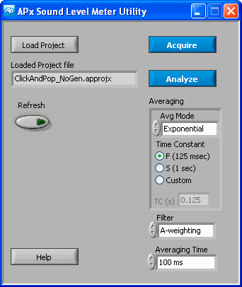
The APx Sound Level Meter Utility.
Connect the outputs of the device under test to the Analog Inputs of the APx instrument. The device should be loaded as it would be under normal operating conditions. For a headphone or speaker output, that typically would mean 32Ω or 8Ω respectively.
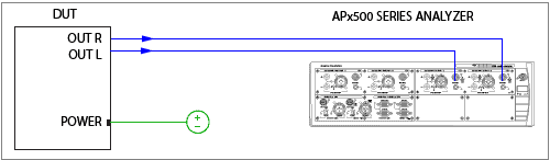
DUT/analyzer connections.
Now, click the Acquire button on the utility to start recording the file. The recording runs for 16 seconds and then stops. During this time, you can turn the device under test on and off, or otherwise manipulate it to try to induce clicks and pops.
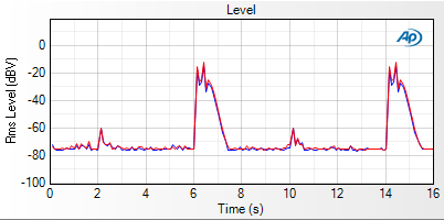
Original APx Measurement Recorder recording.
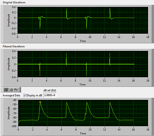
Once the recording has stopped, click the Analyze button. The utility will now display three views in a new window—the original data, the data after it has been passed through an optional A‑weighting filter, and the data after it has been averaged. If you change the filter, time constant, and averaging settings in the window, the graphs will automatically redraw.
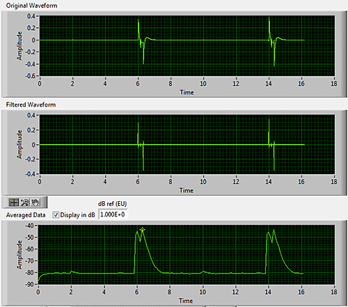
Analysis window, muting the DUT.
Controlling the Device from APx500
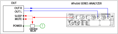
DUT/analyzer connections with APx instrument controlling the DUT.
The second project file, ClickAndPop_SqGen.approjx, employs a clever technique to control the device automatically. Analog Output1 on the APx analyzer is used to generate a square wave that can control logic pins, such as sleep and mute, on the device. Because the square wave generator on the APx instrument has a minimum frequency of 10Hz, we’ve created a waveform file with a 0.25Hz square wave at 0dBFS that’s already loaded into the project. The Signal Generator Level in APx500 is preset to 5volts, but should be adjusted to the required logic voltage.
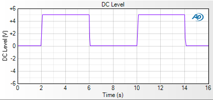
APx generator square wave output.
You can also use the square wave to control a relay that interrupts power to the device. To protect the analyzer output, we suggest that you use a solid state relay or relay buffer and not drive the relay directly.