
Conducting Open Loop Audio Tests with APx Audio Analyzers
In this post, we discuss some of the challenges of open loop audio test and resources available in the APx500 software to make these tests easier.
Closed loop versus open loop audio test
First, some definitions: We use the term Closed Loop to refer to a classic audio test wherein a high-quality audio stimulus signal generated by an audio analyzer is input to a Device Under Test (DUT) and the resulting DUT output signal is immediately acquired and analyzed by the analyzer input section in one continuous operation. Any delay between the output and input signal (typically minimal), is removed during the analysis. Closed loop testing can be used on any device which immediately passes audio, including power amplifiers, audio converters (DACs, ADCs, SRCs), loudspeakers, microphones, mixing consoles, etc.
We use the term Open Loop to refer to a test in which an audio signal is not generated, passed through the DUT and analyzed in one continuous operation. Open loop testing is required for certain types of audio devices. For example, playback-only devices (e.g, Blu-Ray disc players, media players, media streaming devices, etc.) do not have an audio input connector, requiring the stimulus signal to originate as a digital audio file on the DUT (or storage medium), or on a connected server. Another example is recording devices, for which the “output” from the DUT is a digital audio file, rather than a signal passed to an output connector. Many devices – notably PCs, tablets and smartphones – function as both playback and recording devices. For these, the record and playback functions must be tested separately.
A third class of devices requiring open loop audio test is broadcast networks (including traditional radio and television, as well as media streaming applications). In this case, the input to the system is physically separated from the output by a large distance, requiring the use of open loop test techniques.
Closed loop testing is inherently much simpler than open loop. In a closed loop test, the analyzer section of the audio analyzer “knows” what signal is being generated and when it is present. And, the generator and analyzer sections can work together for optimum efficiency. For example, in a stepped sine sweep, transients can occur each time the generator switches frequency or level. To deal with these transients, settling is used in the analyzer section to ensure that readings are taken when the signal has stabilized. In a closed loop test, the analyzer signals the generator to move on to the next point as soon as a settled reading has been taken, minimizing the test time. In an open loop test, this coordination is not possible. Furthermore, a pilot tone or trigger signal is required for some open loop tests so that the analyzer can properly locate the DUT’s response in the incoming signal.
Creating Test Signals for Playback
To test the playback function of a device requires placing a high-quality, known audio signal on the device (or playback medium). Basic audio quality metrics like Level, Gain, Frequency, THD+N, Crosstalk, etc. can be measured using a sine signal. More complicated tests might require signals like stepped frequency sweeps or pink noise, etc. To facilitate creating test signals, Audio Precision offers a Windows application called the APx Waveform Generator Utility as a free download from AP.com (account required). This small program (less than 700 kB) can create .wav files of a number of useful audio test signals at a variety of sample rates, channel counts and bit depths (Figure 1). Many of the test signals are designed to work with the measurements built into Sequence Mode in the APx software. For example, frequency sweeps generated by the utility are included in the list of sweeps recognized by the APx Stepped Frequency Sweep measurement. To supplement these signals, if your analyzer has digital I/O, you can always generate signals in APx and record them in digital loopback to create high-quality .wav files.
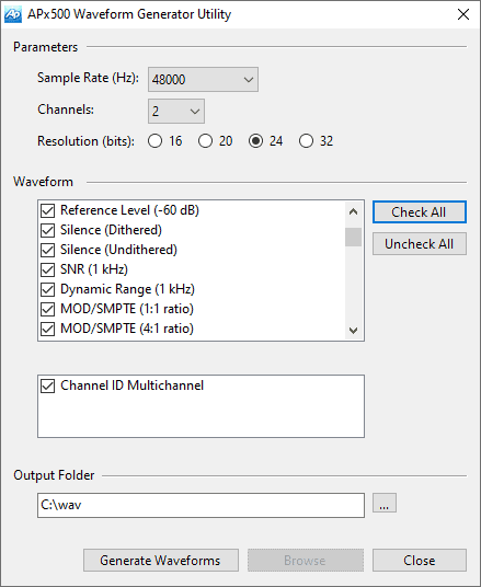
Figure 3. Open loop test of the record function of an audio device.
For frequency response measurements, the APx software has several measurements that (1) can be used in an open loop configuration, and (2) require a specific stimulus: Stepped Frequency Sweep, Multitone Analyzer, Continuous Sweep and Acoustic Response. For convenience, these measurements have the built-in capability to generate .wav files of the stimulus signal. Note: The Transfer Function measurement can also be used for open loop frequency response measurements, but it does not have the ability to create .wav files, because it works with any broadband stimulus signal (noise, music, speech, etc.).
Testing the Playback Function
The process of open loop testing the playback function of an audio device is illustrated in Figure 2. In this case, the outputs from the DUT are connected to the audio analyzer inputs. The steps are:
- 1. Configure the generator and save a .wav file of the stimulus signal.
- 2. If required, encode the .wav file (note: some devices will not play .wav files directly; the file may need to be encoded to, for example, .mp3 format).
- 3. Install the stimulus file on the DUT.
- 4. Start the analysis in the APx500 software.
- 5. Play the test signal from the DUT.
- 6. The audio analyzer acquires the signal from the DUT and analyzes it to produce audio quality metrics.
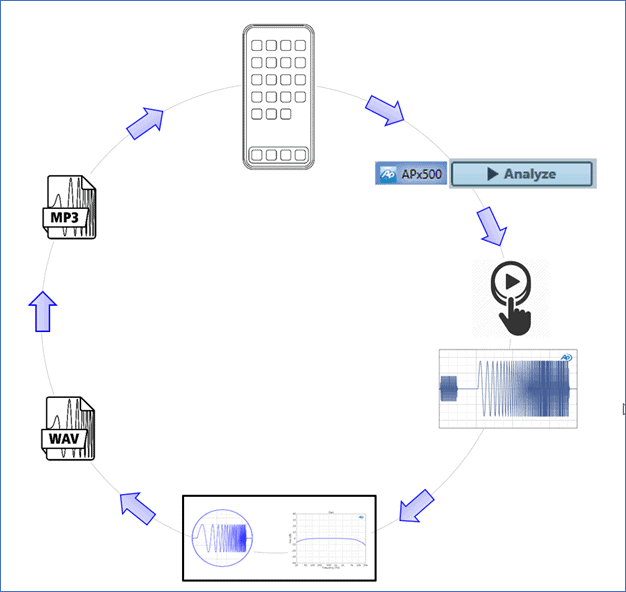
Figure 2. Open loop test of the playback function of an audio device
When testing acoustic playback devices (e.g., a Wi-Fi speaker or Smart Speaker), in an ordinary room, an additional step is required. In this case, it would be best to choose the APx Acoustic Response measurement, which enables windowing the impulse response to remove room reflections. The additional step required is to set the time window after the signal is acquired.
Testing the Record Function
To test the record function of a device, the setup is more or less the opposite of the playback function. In this case, the audio analyzer generator is connected to the DUT inputs, and the analyzer’s input “connector” is set to File (Digital Units), meaning the input will come from a .wav file. The incoming signal from the analyzer is recorded by the DUT to a file which is then analyzed by the audio analyzer. The process is illustrated in Figure 3 and the steps are:
- 1. With the stimulus signal ready to generate in the audio analyzer, start recording on the DUT.
- 2. Start the signal Generator.
- 3. When the signal recording is complete, stop the recording process.
- 4. Save a file of the recording and transfer it to the PC running the APx software.
- 5. If the signal is not a .wav file (e.g., if it is in .mp3 format), decode it.
- 6. Point the measurement at the .wav file transferred in the steps above.
- 7. Analyze the input file in the APx measurement.
For acoustic devices, some additional steps may be required. For example, suppose the signal is being generated by a mouth simulator (a special loudspeaker with prescribed opening dimensions for generating speech signals). In this case, additional steps would be required to calibrate the mouth simulator and equalize its output to have a flat frequency response, so that it faithfully reproduces speech signals.
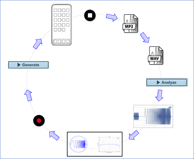
Figure 3. Open loop test of the record function of an audio device.
This concludes our overview of open loop audio testing in APx500 series audio analyzers. We encourage you to take advantage of these features for your open loop test needs.
Learn about applications, and you’ll get tips and tricks of test and measurement
Read more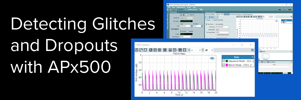
APx500 Software provides two distinct tools for verifying a device's capacity to playback a signal for an extended period of time.
Read more
Learn how to conduct measurements on a batch of devices and display results on one graph for comparison.
Read more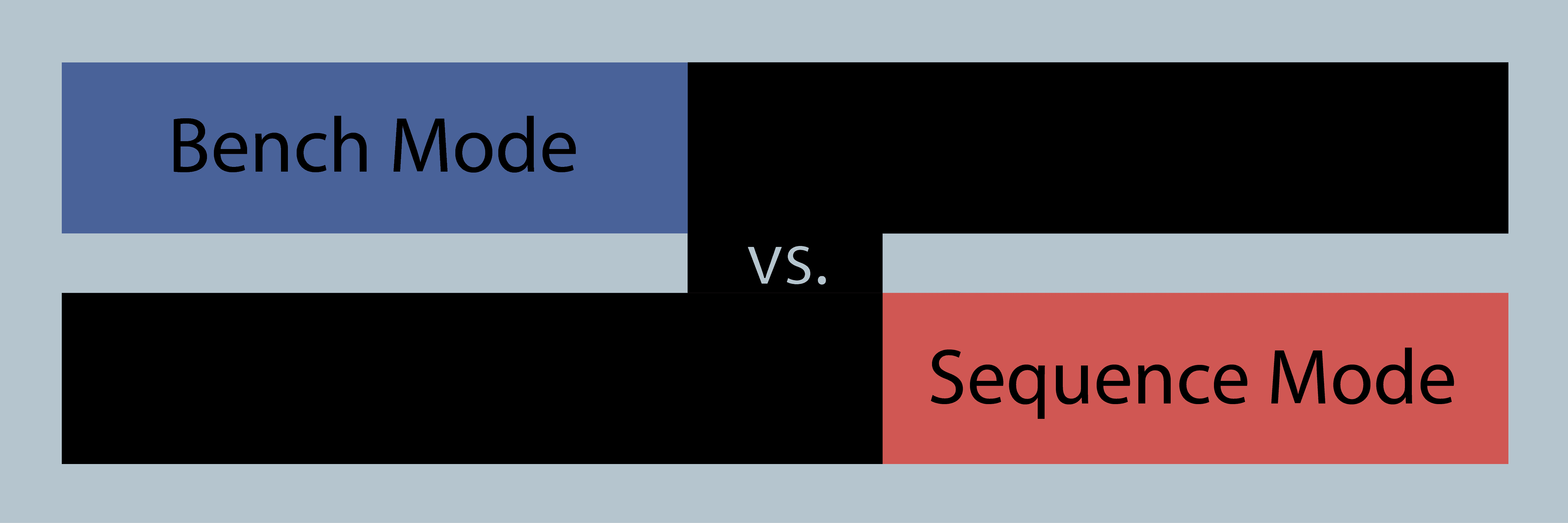
These two modes of operating the APx500 software represent not just two different approaches to how the software is used, but also two different signal processing approaches.
Read more